
Senior Project, 2024 - Current
Primary Skills: Thermal Design, 3D CAD, Electrical Design, Aerodynamics, Robotics, 3D Printing
Software/Programming: Solidworks
Deliverables and requirements:
Create a flying machine that can deliver emergency aid materials to hard to reach areas. It will be a vertical take off and landing (VTOL) unmanned aerial vehicle (UAV) that can fly 5 miles on one charge while carrying up to 1 pound of cargo. It must be able to take off and land in flat, but not large areas (no need for a take-off track). It will be remotely piloted and utlize cameras, GPS, and audio to fly to a far location and interract with a human once landed.
My contributions & timeline:
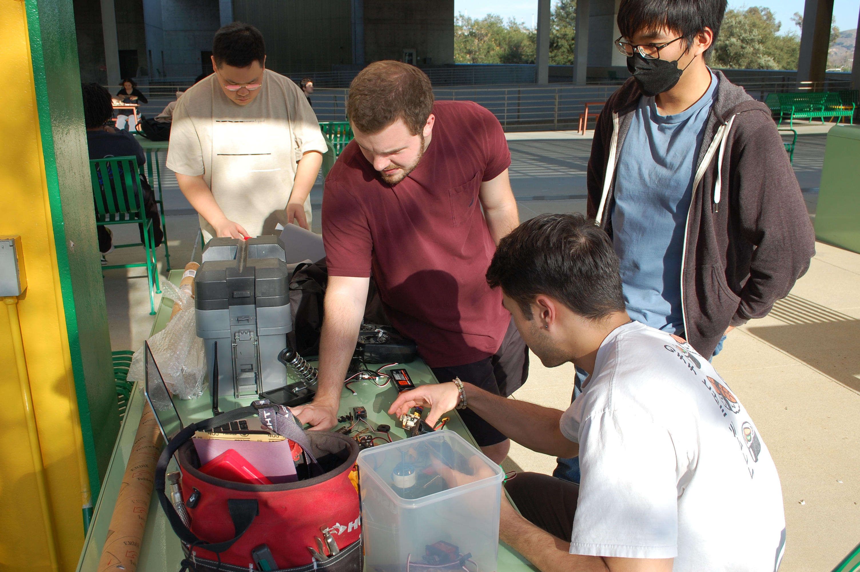
Fig 1. Team working on part compatibility
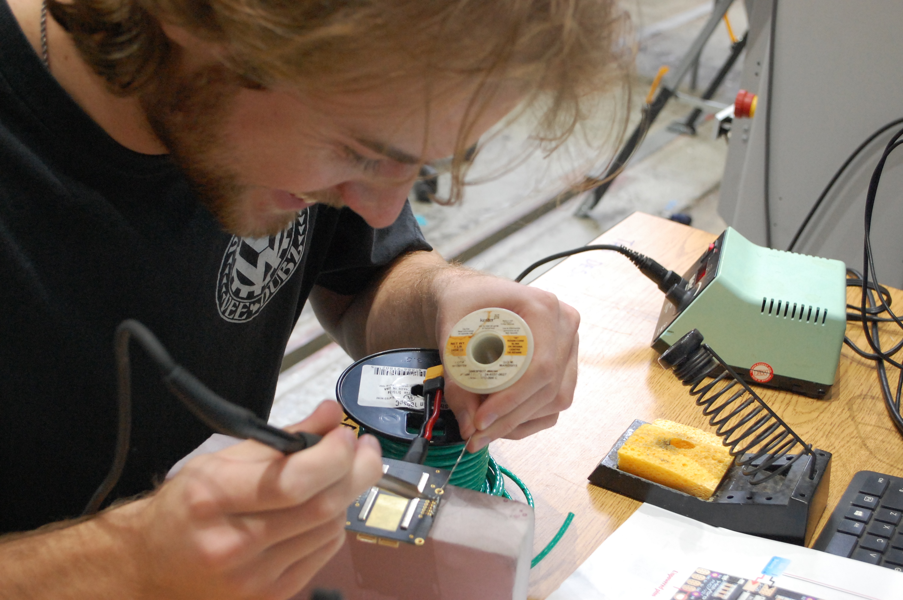
Fig 2. Me soldering a power distribution board
So far, the electrical design has been created and parts have been ordered. Putting parts together will be conducted over the coming weeks.
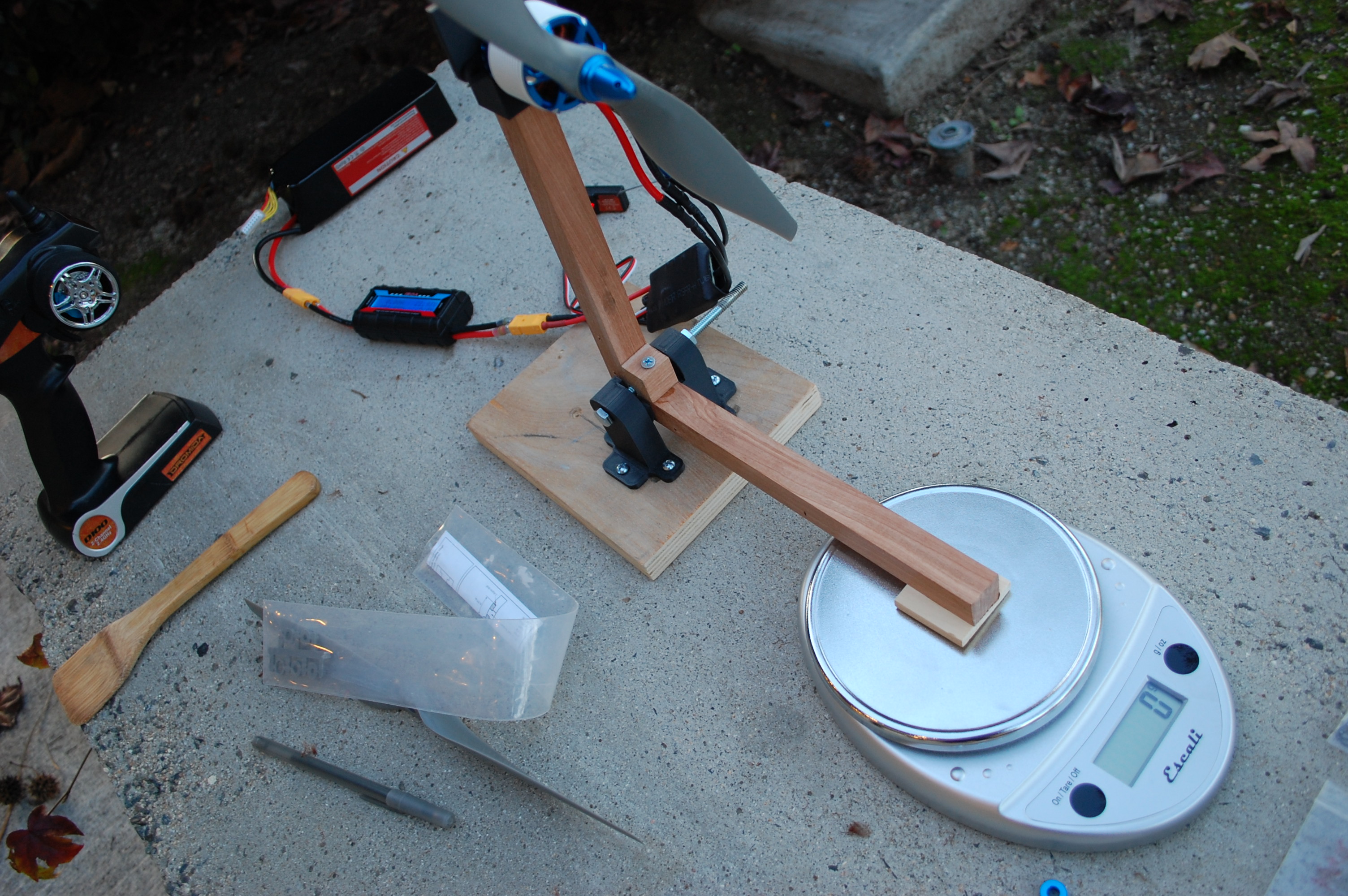
Fig 3. Custom thrust stand to record force vs. current
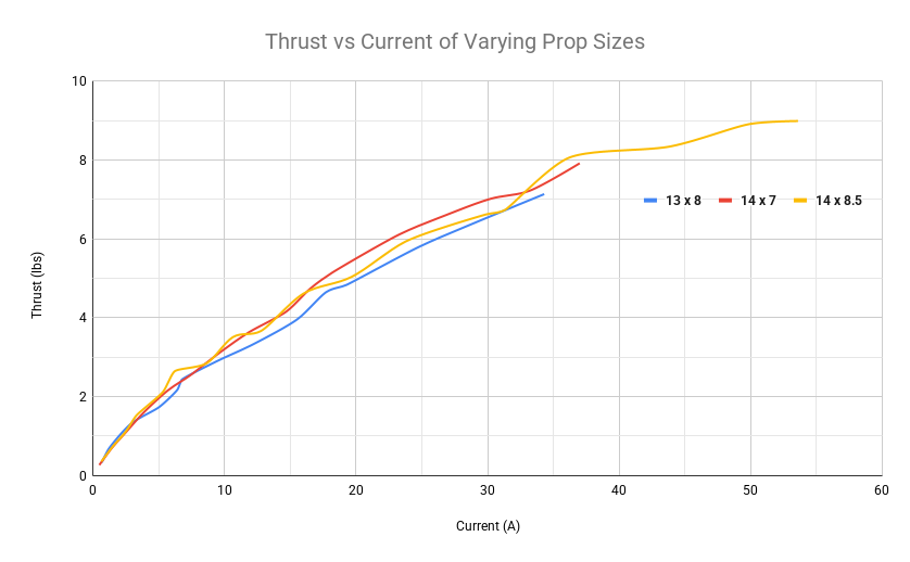
Fig 4. Thrust curves obtained with varying prop sizes
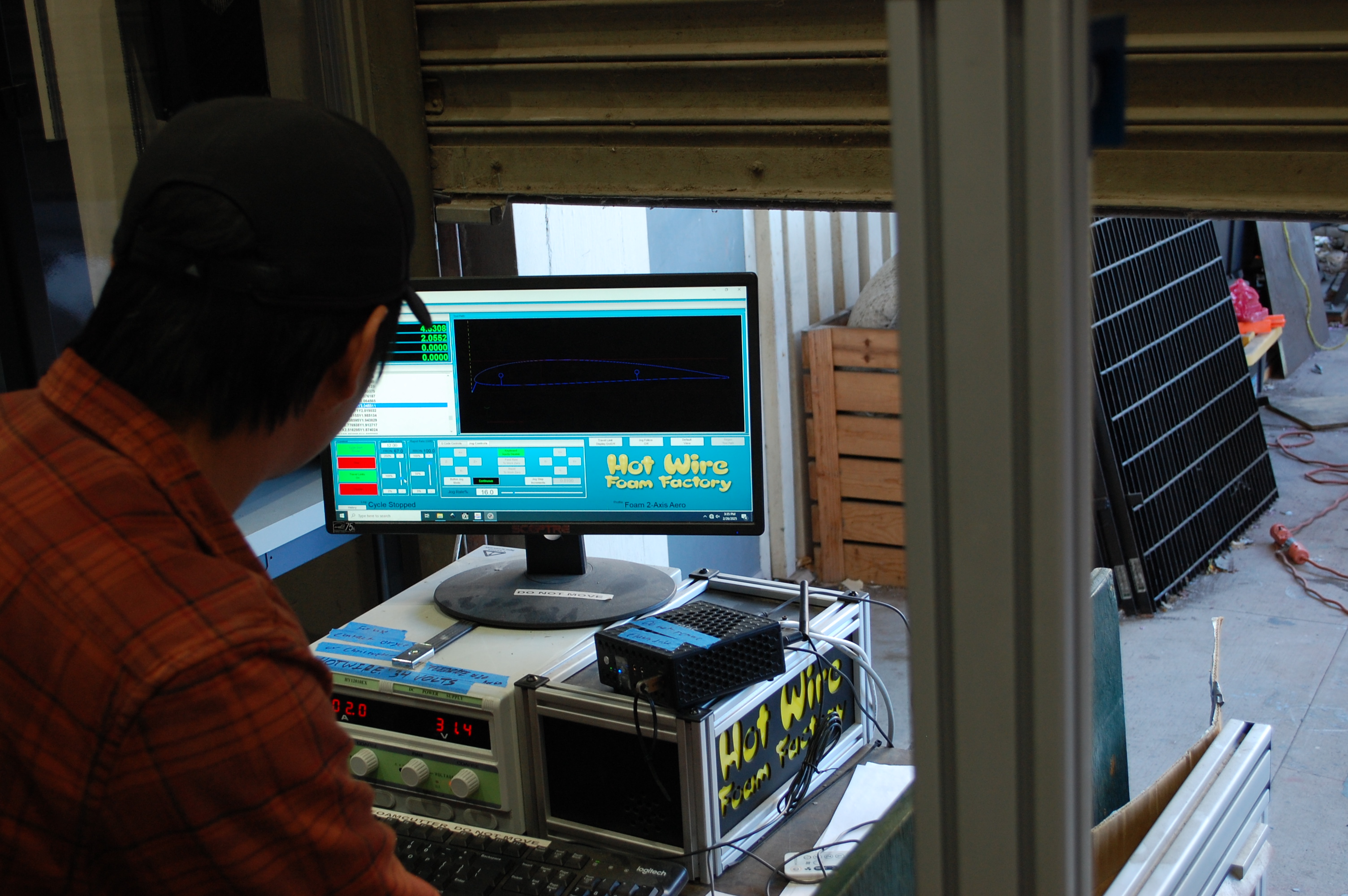
Fig 5. Software running the foam cutter to shape the wings
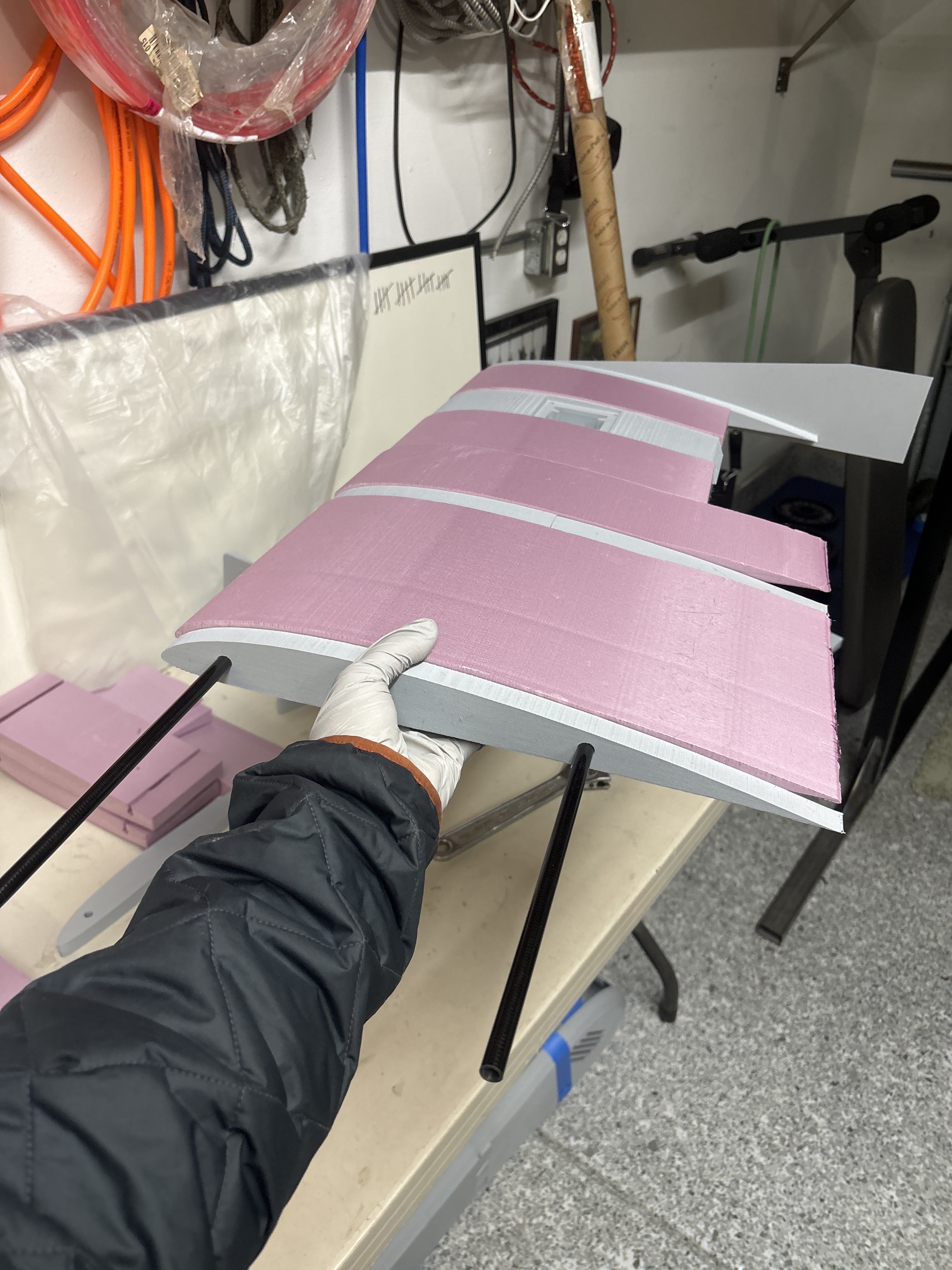
Fig 6. First wing assembly
Outcomes:
This project is in progress.
Class Project, 2024 - Current
Primary Skills: Electrical Design, Control Systems, Material Science, 3D CAD & Printing
Software/Programming: Arduino, C Language, Solidworks
Deliverables and requirements:
A relatively simple deliverable: Create a system that uses magnetic fields to make a mass suspend within the air for 30 seconds, handling vibrations and other random inputs.
My contributions & timeline:
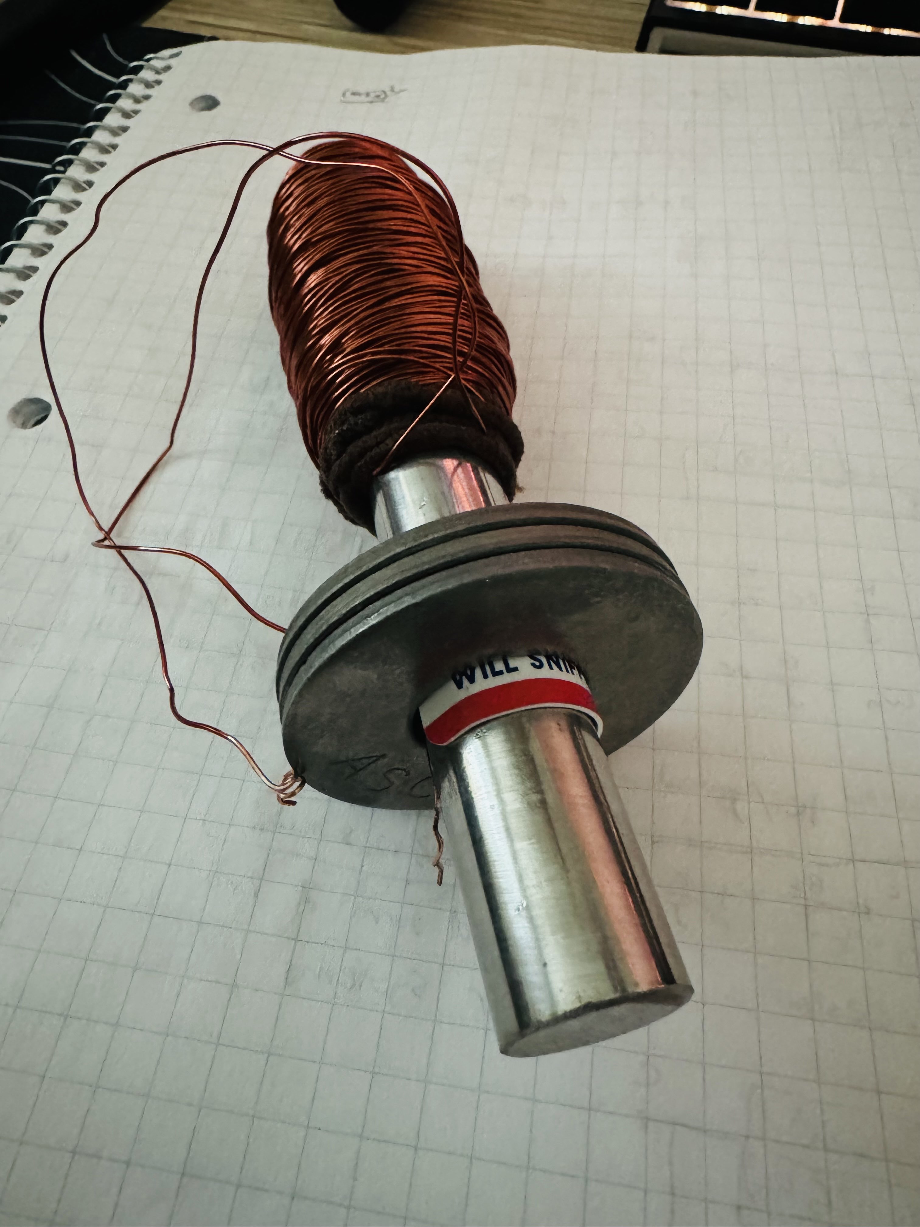
Fig. 1
I had extremely limited knowledge of electromagnets, so I started my research there. I elected to construct a powerful one as I wanted the distance of suspension to be large. I needed a suitable core. I believed that any metal would do, but turns out only very specific materials can be used. After diving into relative permeability and flux saturation, I had my eyes on materials that were simply out of my price range. I ended up finding a martensitic stainless steel rod and figured it would work well enough, even though some low carbon steel would have sufficed as well, although neither of these options were optimal performance-wise.
I had an 11.1V LiPo battery lying around, so I based my calculations on that. Thinner wire had higher resistance and could handle less current, so choosing a suitable gauge was crucial. After estimating the length for 700 coil turns, I decided to use 22AWG magnet wire, as it would provide roughly 4.5 ohms of resistance from length alone, and thus about 2.5 amps, plenty of strength. I then hand-wound the electromagnet, finishing half of a movie in the process. To both improve the magnetic field (by controlling the field’s flow via ferritic steel) and make the physical contraption able to be held up, I chemically removed the zinc-plate of several washers, and put those in place, finishing the electromagnet [fig. 1].
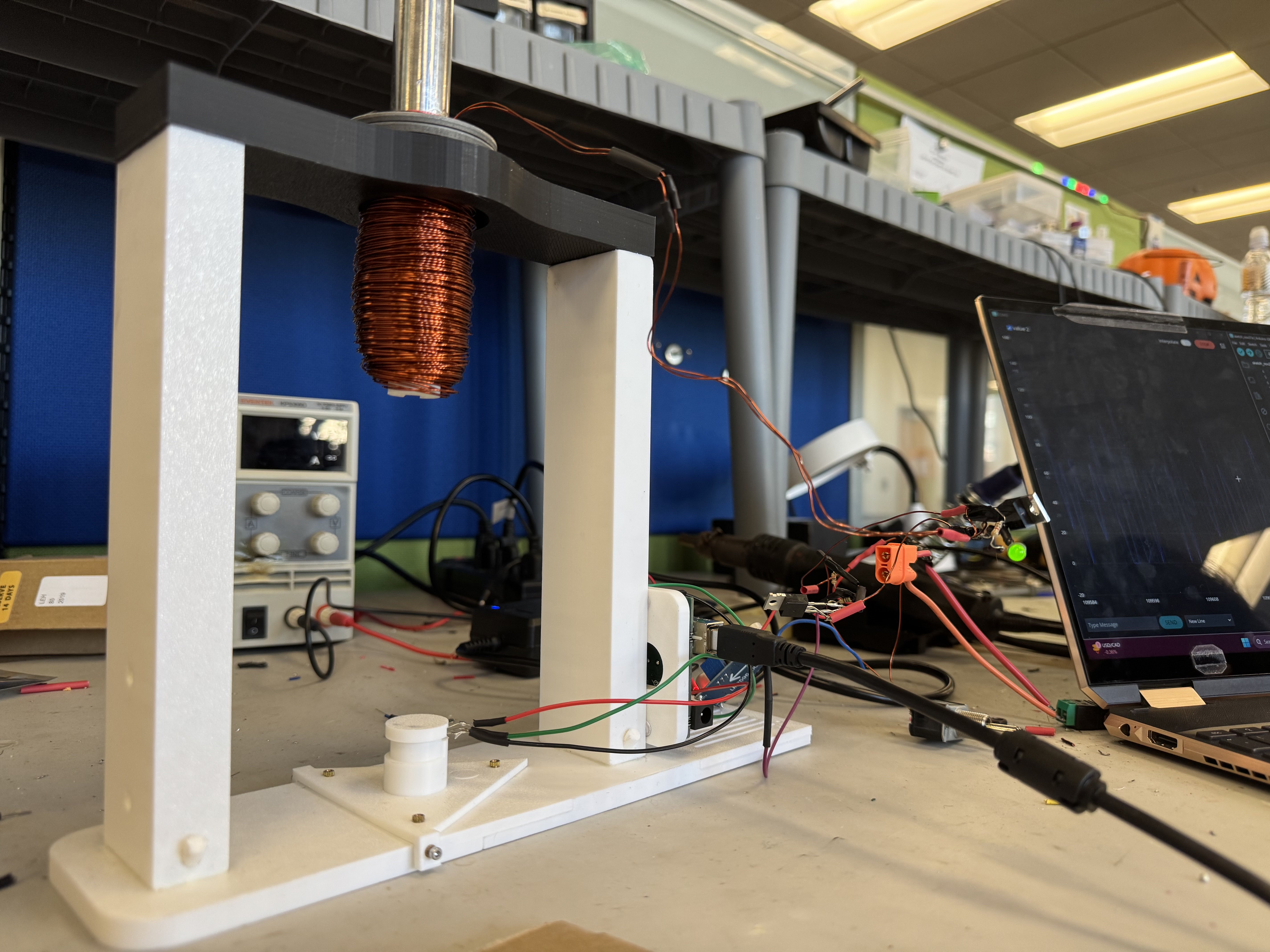
Fig. 2
After I designed a basic electrical circuit, my team and I collected all the necessary components from across the internet, soldered it all together, and began testing [fig. 2]. Through trial and error and an amazing amount of bug fixes, the circuit was constructed and did as it should.
Lastly came the integration of the software. This system used a microcontroller, where we would apply our controlling software. Utilizing PID, we had to tune for its position, velocity, and error in position. After many close, yet unsuccessful attempts, we figured our Arduino Uno’s 40 MHz clock speed was simply too slow. We upgraded to a basic ESP32, which clocks in at over 200 MHz, and resoldered and reconfigured the system to help integrate it.
Outcomes:
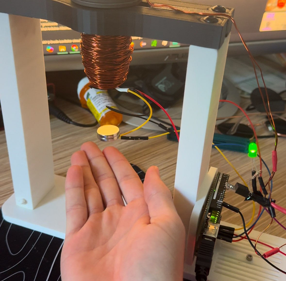
Fig. 3
Despite the microcontroller upgrade, the system would not remain stable. We exhausted our resources, such as the professor, other students, the text and online resources, and we were unable to achieve hovering for more than a few seconds [fig. 3]. No team reached 30 seconds of hovering, and it was the professor’s first time trying this project with students.
For my team’s system, we elected that due to the geometry of the electromagnet, we were unable to put in more hall effect sensors, which would have helped remove noise caused by the electromagnet’s magnetic field via difference. The derivative function of the PID controller was simply affected too negatively to provide accurate results, preventing stability.
It was a great project despite these setbacks, as the professor liked our design and I learned more about electronic integration than ever before. We were simply thrown into the deep end without much instruction or assistance, and we managed to mostly pull through and gain valuable knowledge.
Class Project, 2024
Primary Skills: Stress analysis, 3D CAD, Drafting, Industry-style work
Software/Programming: Solidworks, Powerpoint
Deliverables and requirements:
“The function of the TCV is to mix a cold stream of fluid with a warm stream and output a flow of mixed temperature fluid. In order to properly control the system, the TCV needs to minimize inlet flow fraction of cold fluid at 0 degrees C and also minimize flow fraction of hot fluid at 20 degrees C. The TCV shall interface with .375 IN x 0.028 IN THK CRES 316 interconnect tubes, be compatible with CFC-11 as a working fluid, mount to a horizontal surface, and the design should assume infinite life.”
These were the three sentences provided for the 8 week project. After decoding the acronyms, clarifying many aspects and adding new requirements given the circumstances this TCV will be used in, we summarized the requirements/conditions into a list:
My contributions & timeline:
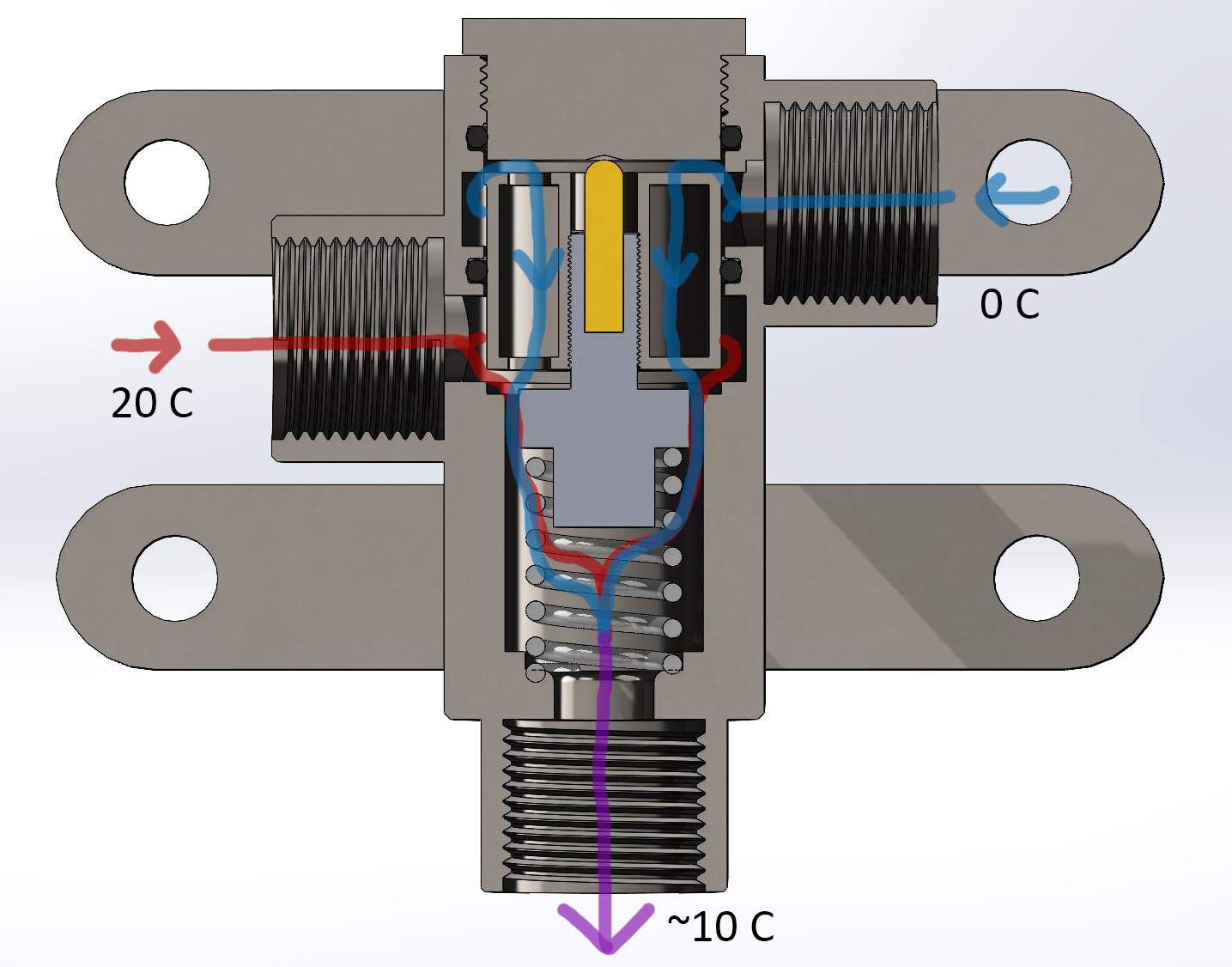
Despite being in a four-person group, I took up much/all of the ideation of the functionality, part selection, CAD work, drafting, and stress calculations. To start, we conceived the idea of using a thermal actuator to produce movement from temperature. Essentially, using thermal expansion of a material going through a phase change to generate force. In order to average out the hot and cold flows, this movement needed to move a “door” that at the maximum mixed temperature (20°C), stops hot flow and maximizes cold flow, and vice versa at the minimum mixed temperature (0°C). Essentially, if the mixed output flow is too hot or cold, it will balance the in-flows to reach a desired equilibrium, which we set to ~10°C.
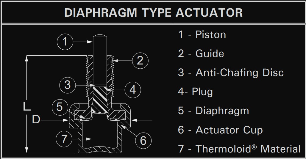
Fig. 1
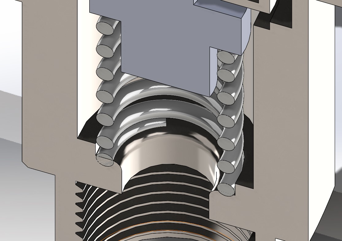
Fig. 2
Now that the general functionality had been established, we started looking for parts, preferring COTS (commercial off-the-shelf) as they are cheaper, faster, and have established stats. I focused on the thermal actuator, spring, and SwageLoks.
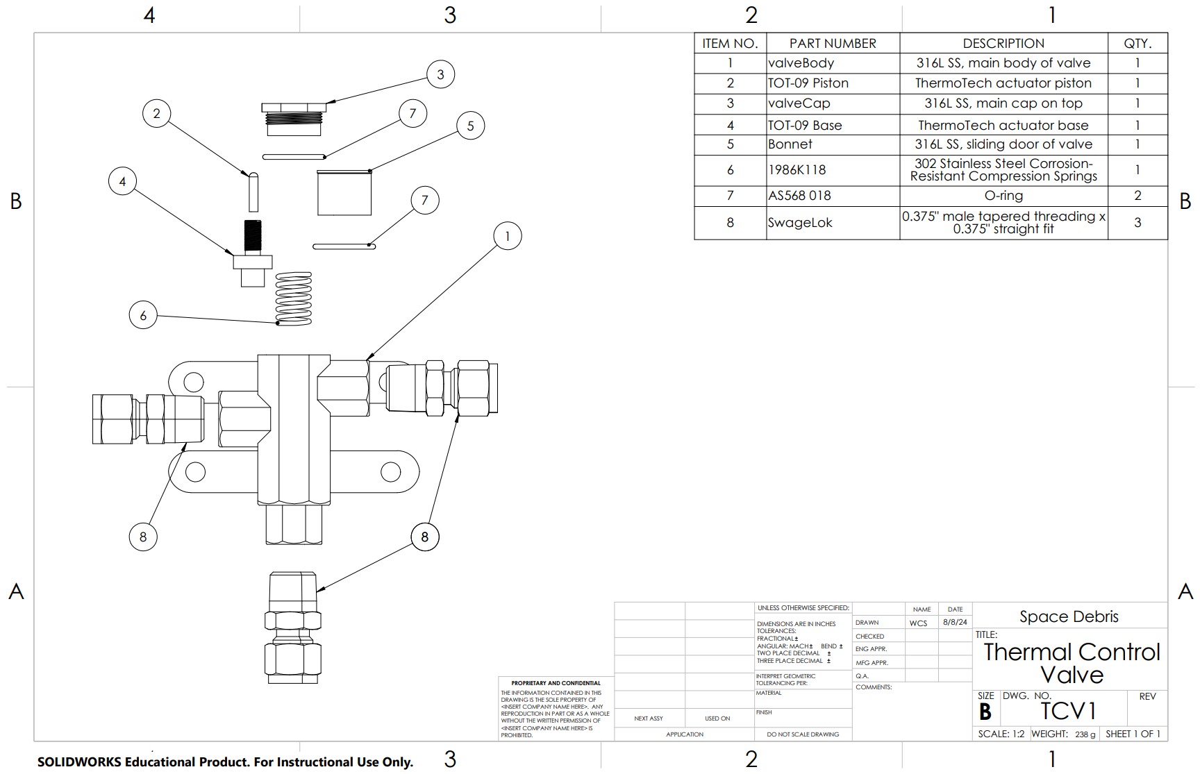
The actuator selected was the TOT-09 from ThermOmegaTech [fig. 1]. The main expanding material is called Thermoloid® and the specifics for it are proprietary, but they state they can customize the formula to meet force/temperature needs within certain ranges. Thus, an actuation force of 9.2 N at 0°C and 18.4 N at 20°C was quoted. The limit for the TOT-09 is 110 N, giving us a FOS of 6.
The force values above were selected as they work with our selected spring: the 1986K118 from McMaster-Carr. This stainless steel spring had the correct dimensions to fit snugly around the base of the thermal actuator, was wide enough to accommodate the opening, and was made from the desired stainless steel [fig. 2]. It had a stiffness constant of 9.2 N/mm, thus when combined with the thermal actuator, there would be a 1 mm deflection when the temperature changed by 20°C. With this value in mind, the whole design of the valve could be formulated [fig. 3].
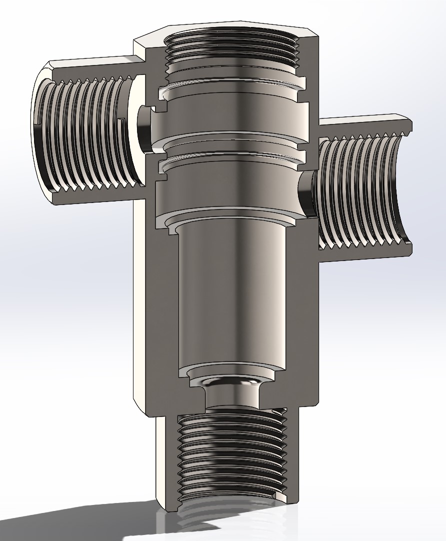
Fig. 3
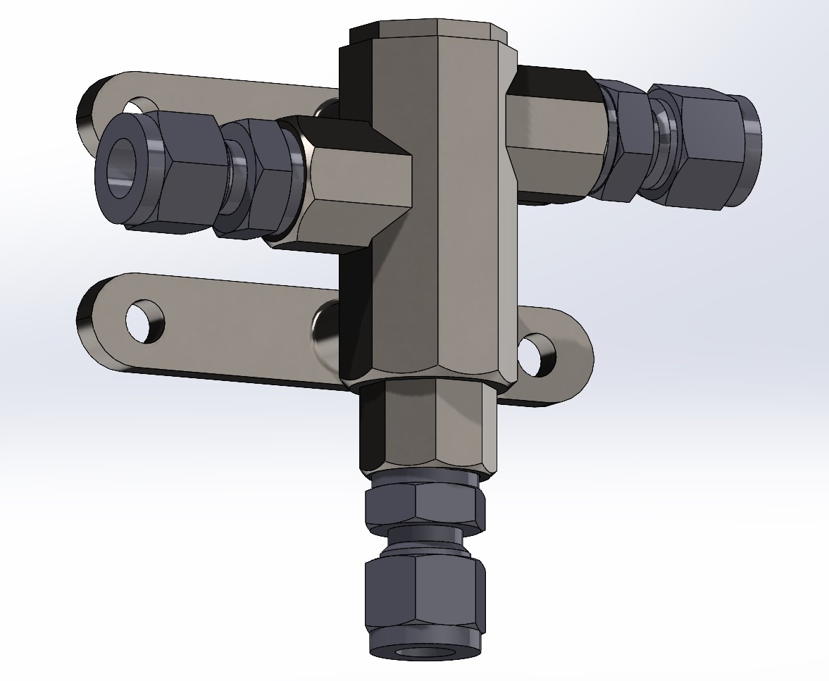
Fig. 4
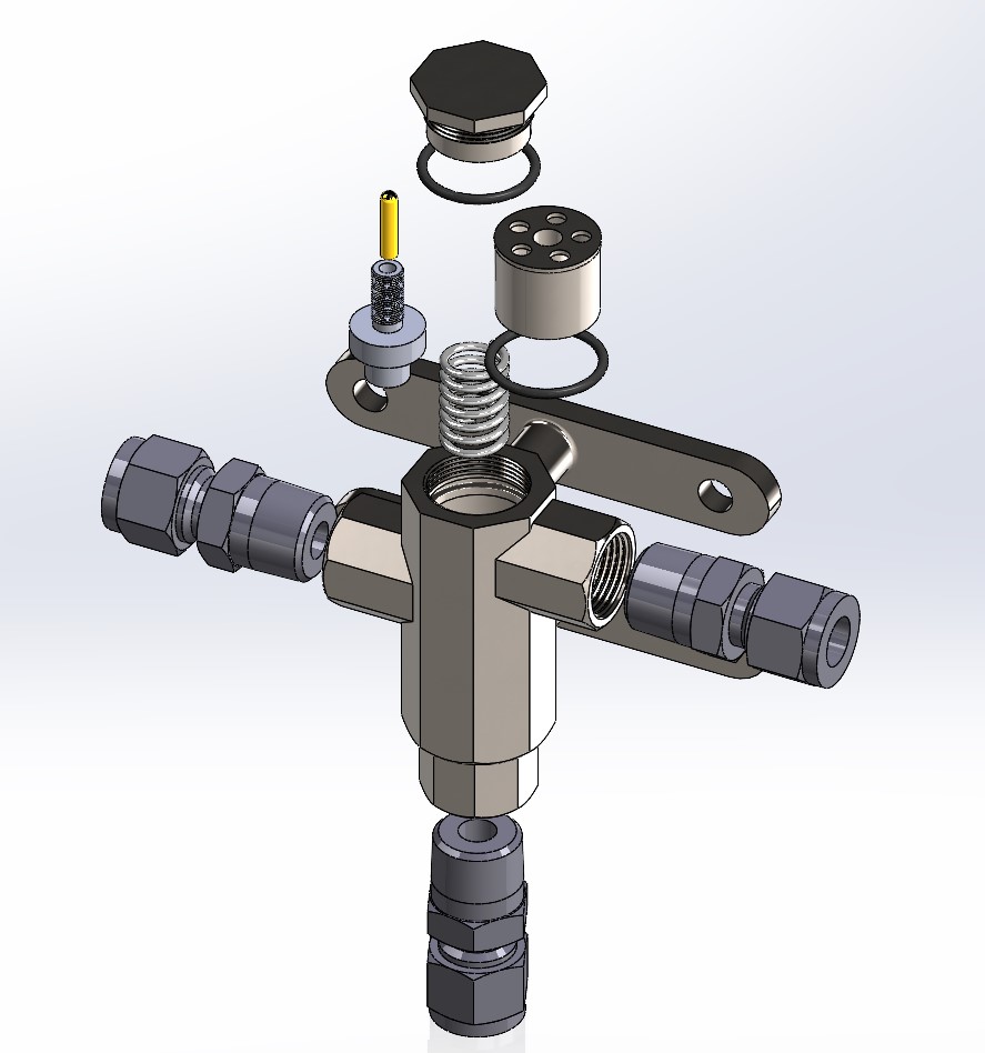
I designed the valve’s dimensions to accommodate many aspects, including the sliding door mechanism, structural stability, strength concerns, and the ability to assemble the entire product. The material chosen was 316L stainless steel due to its strength and corrosion resistance. There were two inlet holes, one outlet, and one assembly hole. The inlets/outlet had tapered threading combined with a NASA-endorsed thread-locker (Loctite® 242) to prevent seepage when interfacing with the SwageLoks. The assembly hole used linear threads with thread-locker as well as an o-ring to finally seal the interior. Both O-ring grooves were designed to the specifications laid out in the Machinery’s Handbook. Following the fluid flow through the machine, there are no areas smaller than that of the piping, preventing bottlenecking. After conducting pressure calculations, it was deemed the minimum valve wall thickness was about 0.01mm. The thinnest section was elected to be 2 mm, plenty larger than the minimum to accommodate additional stresses from acceleration and vibration, and as the entire part was exceptionally small, weight was not too much of a factor.
Outcomes:
The final design was built to withstand the forces and environment that comes along with extended space flight, while remaining functional for far longer than the expected project duration. Its lowest factor of safety came from the spring due to fatigue, landing at 2.2. Another major concern was the force the piston (golden part on the thermal actuator) would exert onto the valve cap before launch, as temperatures outside can greatly exceed 20°C. However, a safety factor of 5 exists for the whole actuator at 20°C, therefore any reasonable temperature should not adversely affect the structure.
The final design [fig. 4] achieved every requirement, and also utilized materials/components that can withstand the harshness of space travel, such as high accelerations, zero pressure, and radiation exposure.
Class Project, 2023
Primary Skills: Electrical/PCB Design, Component Integration, Teamwork
Software/Programming: Eagle, C (language), Powerpoint
Deliverables and requirements:
My contributions & timeline:
I was the lead for the electrical subsystem, which includes the design and fabrication of PCBs and the assurance of effective connectivity throughout the robot. Despite being the lead on the electrical subsystem, I actually had nearly zero experience in that arena at the time. This meant my first several weeks were spent learning as much about circuit design as possible.
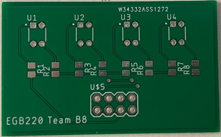
Fig. 1
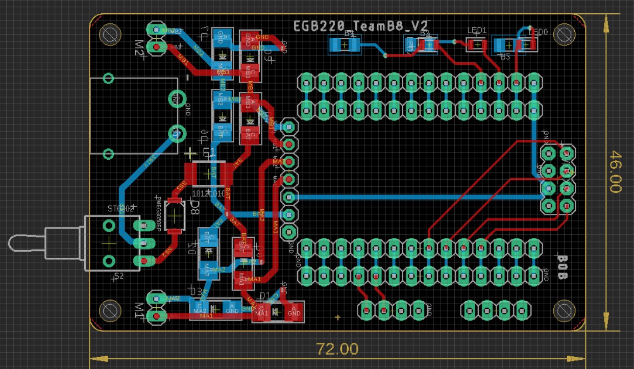
Fig. 2
To design the PCBs, I learned to use Eagle, a circuit board designing software. We had three “ordering events,” where those were the only times PCB designs could be sent out to be manufactured (to save money with bulk orders). The first one was small and done mostly as a practice, but it was still used to assemble the sensors and connect them to the microcontroller [fig. 1]. The second round, a couple weeks later, was where I really needed to effectively apply my limited knowledge. This one was the central board, housing the microcontroller and thus acting as the nervous system of the bot. It needed to correctly connect the motors, sensory components, and power systems to the microcontroller while regulating voltage/amperage and remain as small as possible, considering price was by the square centimeter. I thus designed a PCB to match all of these necessities and it was sent out [fig. 2].
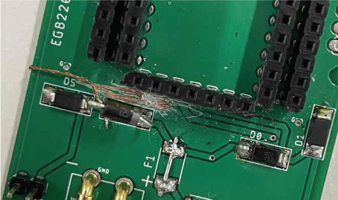
Fig. 3
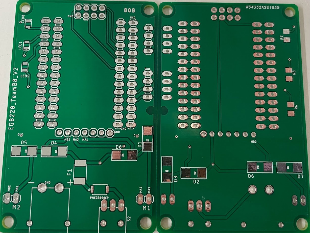
Fig. 4
However, after receiving the physical board, nothing happened. After ensuring it was turned on, I became extremely worried that my lack of knowledge and experience had caught up to me. Fortunately, after rigorous testing and analyzing, I discovered a single misplaced trace (connection). I proceeded to carefully scratch out the incorrect trace and solder emergency wire (wire with covering stripped off) to mimic the correct layout [fig. 3]. This luckily worked, and I proceeded to fix the issue in Eagle, resulting in our third round providing a functional PCB that worked as intended [fig. 4].
Additionally, I helped in every other subsystem any moment I could. This included stress testing the 3D printed chassis, experimenting ways to distinguish between different colors with a non-color sensor, and determining the best driving patterns.
Outcomes:
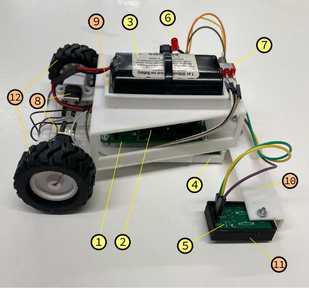
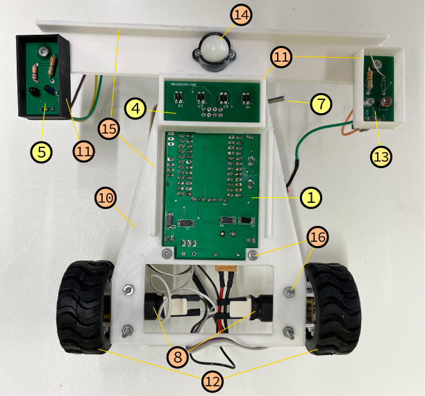
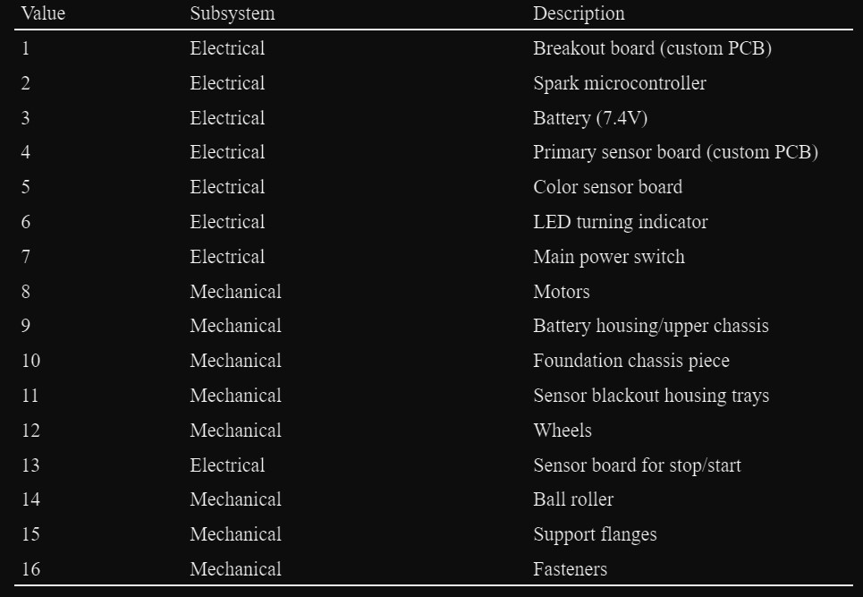
Met the deadline and delivered on all requirements. My team successfully constructed the chassis, designed/implemented the electrical and sensory systems, and wrote the programming for the autonomous line-following robot while staying under budget ($203/220). This was not without several hiccups, many of which were directly due to my own oversights. Despite this, we pulled through and finished strong, and I learned a ton about PCB design, electrical component integration, microcontrollers, and simply working with a team and delivering a product within a budget.
Class Project, 2024
Primary Skills: Strengths of Materials Analysis, Communication, Teamwork
Software/Programming: Powerpoint
Deliverables and requirements:
Research different materials and their properties to find out why they are chosen in a specific application, and present the information found. Select several materials for this application to explore in-depth and run FEA simulations to determine their feasibility. Optional: Design and conduct an experiment that explores this idea through actual testing utilizing industrial equipment.
My contributions:
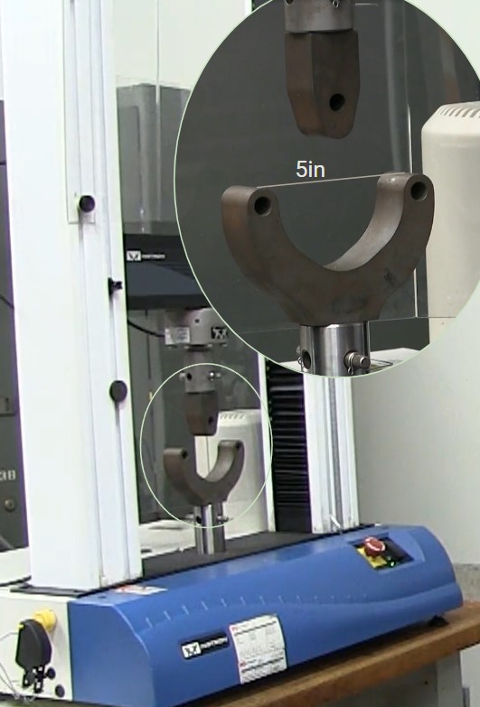
Fig. 1
Due to my history with building longboard decks from scratch, we elected to run with this idea as our topic as I had some experience and understanding of what properties are sought out in a deck (and I was genuinely curious on what other materials I could safely use to build with next). The actual testing aspect was optional, but due to the variability of wood properties and its relatively high accessibility, we found it better to personally find the values we wanted through experimentation. Plus, it was a lot more fun.
The materials we selected were maple, generic plywood, baltic birch plywood, and acrylic. There were two specimens of each material for increased redundancy. The experiment consisted of putting each specimen through a 3-point bending test [fig. 1], where it would be pressed down at the centerpoint of two supports until failure occurs, resulting in a force/deflection graph [fig. 2]. Each specimen had vastly different cross sections, so those must be considered as context for the values shown in the graphs.
Using data points derived from the graphs, values for ultimate strength and Young’s modulus could be calculated. Additionally, in order to compare things like weight and price between the decks, there needed to be a common reference point. I elected to use flexibility (deflection) for this, considering it’s an inherently subjective parameter and would be impossible to rank. Thus, I calculated what cross-sectional size would be needed for each material to exhibit a similar bending pattern under load (based on experiential data), and with this we could find their respective weights and costs.
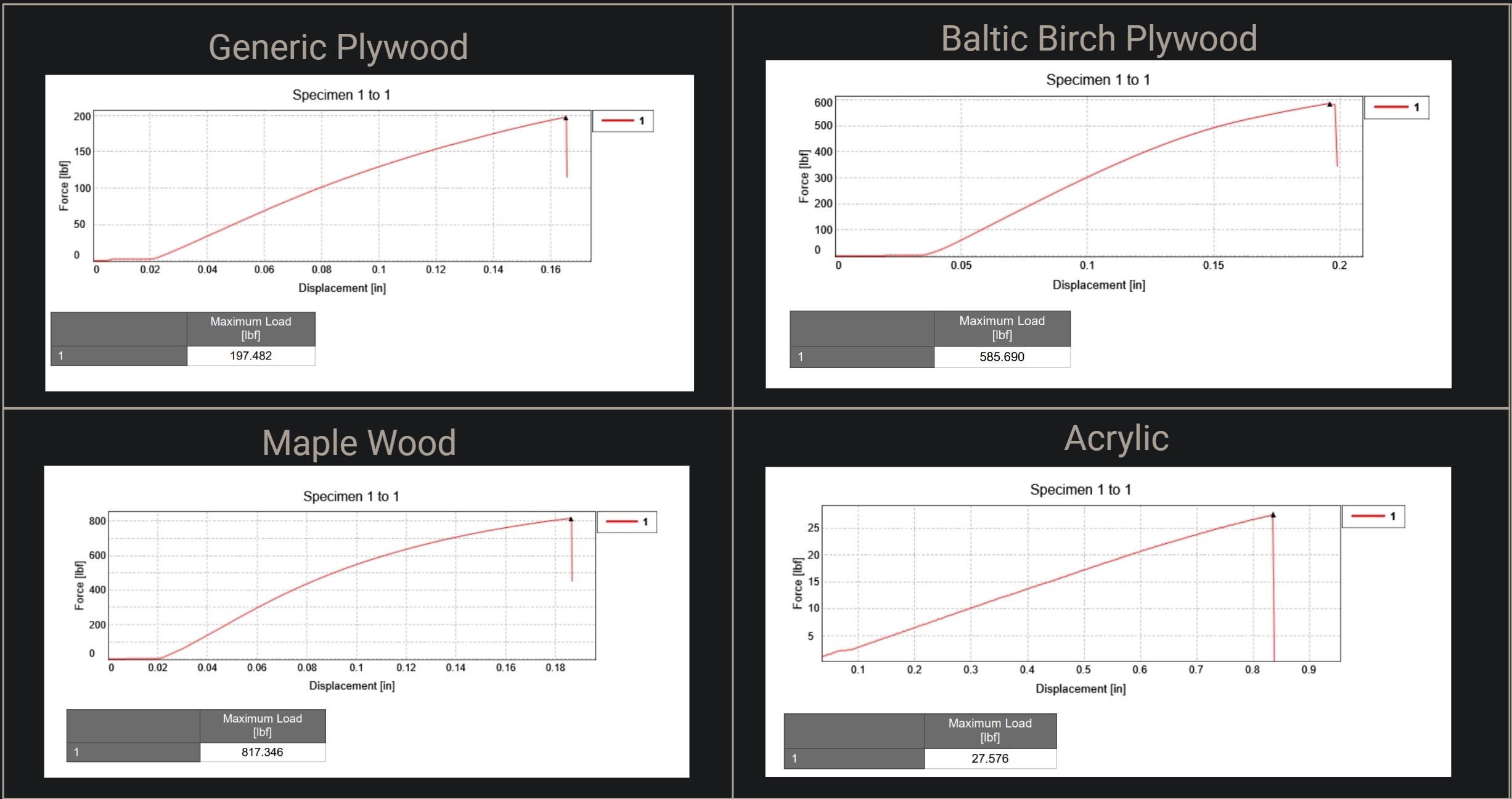
Fig. 2
Outcomes:
A merit table was produced from all of our experimental and researched data to determine which material is superior when used for longboard decks [fig. 3]. Both baltic birch ply (“double ply”) and maple came out on top, with acrylic and generic ply coming up far behind. Here is a summary of the findings:
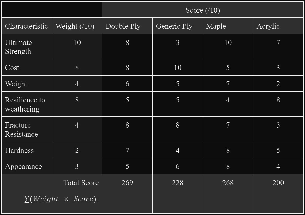
Fig. 3
Class Project, 2024
Primary Skills: FEA
Software/Programming: Siemens Femap
Deliverables and requirements:
Given the model, cut out unnecessary aspects and introduce a FEA to interpret the model’s reactions to external forces.
My contributions & timeline:

Fig. 1
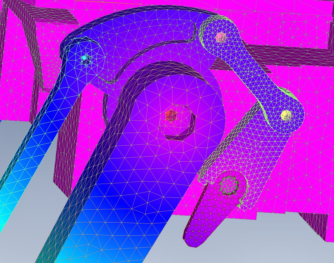
Fig. 2
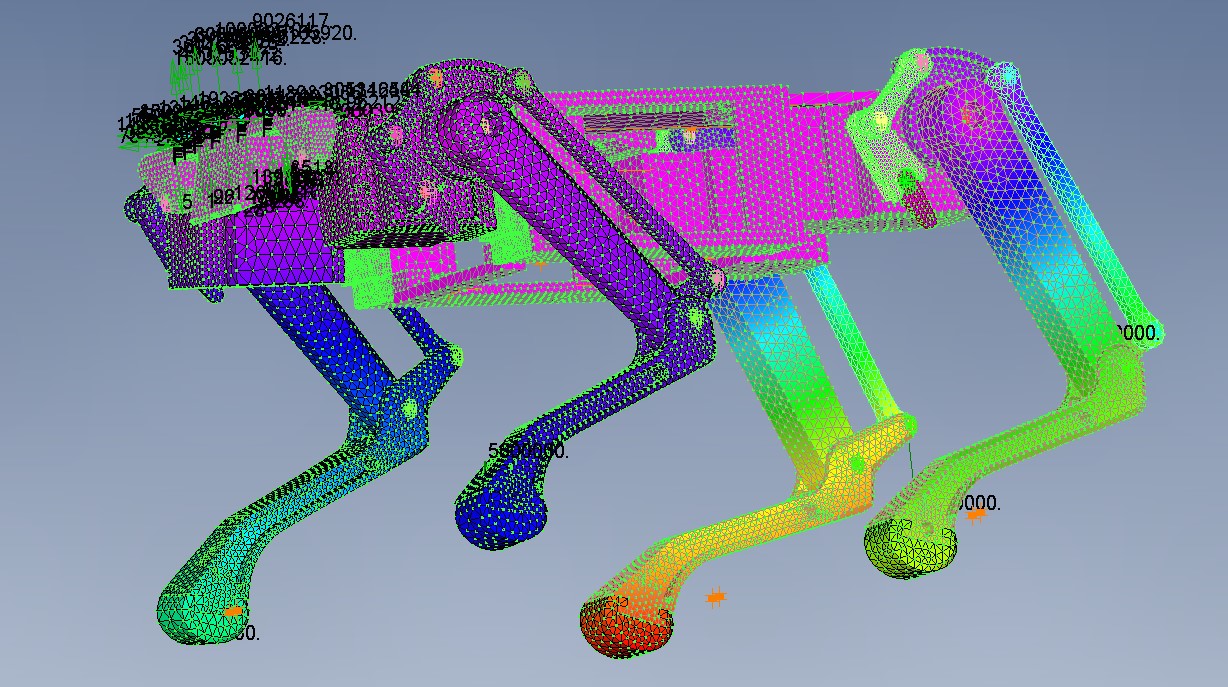
Fig. 3
The model was given as an accurate depiction of the real world robot, thus including every bolt, groove, and part required. When beginning, it was necessary to remove such additions as they increased the model’s complexity without adding structural strength. In a similar vein, parts were simplified again for the same reason with the use of Femap’s modeling tools.
This was followed with meshing for every part, and then combining parts together. This included creating joints that allowed movement in only specific dimensions [fig. 1 & 2]. Many errors occurred along the way, each being solved with many debugging strategies.
Outcomes:
The system was successfully modeled and followed expected behavior given certain inputs [fig. 3]. All reactions were realistic and zero errors persisted at the end. Reaction forces, stresses, and translations were all recorded and reported.
Now, I can implement FEA on future structural projects with reasonable confidence, another tool to use in design.
Skills
Several of the potentially applicable skills I have.

Mechanical Design
3D CAD (Solidworks, Autodesk), FEA (Femap), mechanical assembly

Programming Languages
MATLAB, Java, C#, Python, HTML/CSS

Electrical Design
Circuit design, PCB creation (Eagle), soldering/wiring

Manufacturing
Rapid prototyping, hand tools, grinders, sanders

Software
Solidworks, Femap, Excel, Adobe (PS, Illustrator), VS Code, Eagle, Blender